- Prep work
- Installing the new outer joint housing.
- Installing the reinforcement rib
- Installing the hardware
Wisefab BMW E36/E46 DIY Drift Kit installation guide.
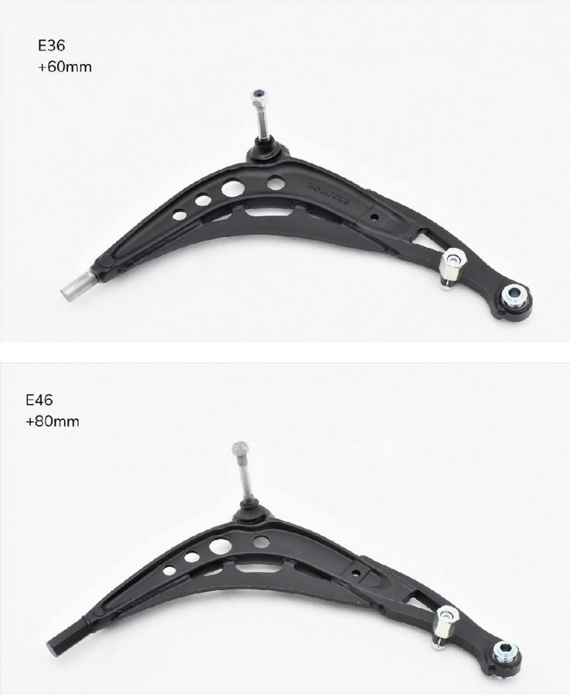
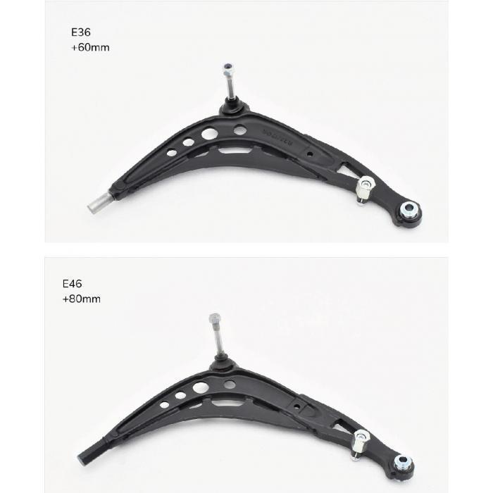
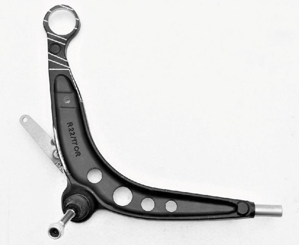
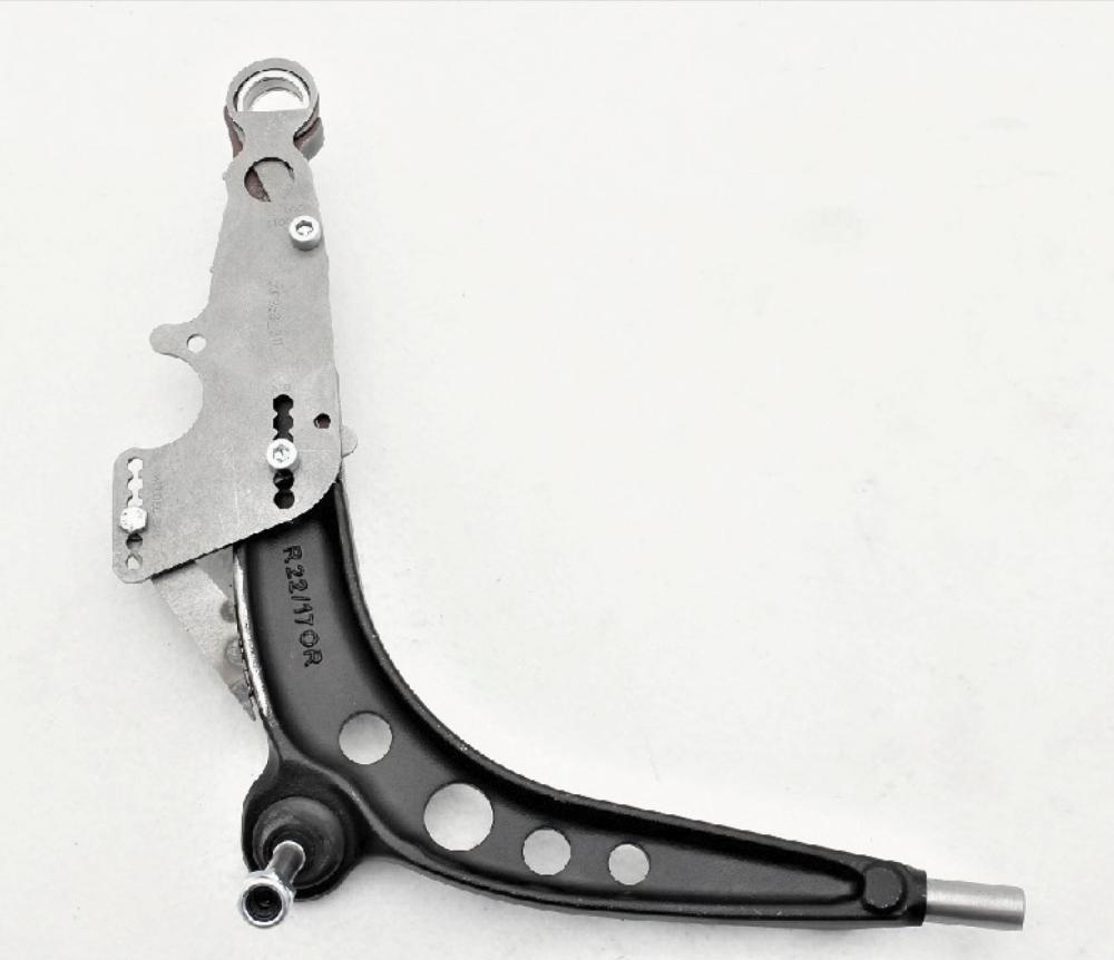
This manual describes the modification process of the E36 control arm. We advise you to use only non-M 91-99 steel control arms with 49mm outer ball joint. We have used the right control arm for this installation guide. With Wisefab BMW DIY kit you can widen the control arm from 30 up to 80mm. Cutting template is included. For maximum usable lock on the BMW E36 chassis you can widen control arms 60mm per side. For the BMW E46 you can widen the control arms up to 80mm per side when maximum usable lock. Depending on tyre size and lock stopper position, the tyre may rub on the anti-roll bar when in full lock. Factory struts usable on this Wisefab BMW DIY kit. Coilovers and/or adjustable top mounts are advisable.
- For inner tie rods use Ford/Mazda part number EC0132240 or YL8Z3280EA.
- For tie rod ends use Ford/Mazda part number EC0132280 or 5L843289AA.

When purchasing tie rods make sure the inner end (rack side) is M14x1,5 male and outer end M16x1.5 male thread.
Make sure that You have all the required tools on hand. You will need:
- Safety equipment (welding mask, goggles, gloves)
- Fine tip permanent marker, measuring tape, scissors
- Wrenches
- Angle grinder with cutting and sanding discs, burr removal tool (die grinder)
- Welding equipment
Use Wisefab templates on this install. We have included a hard copy with the paper user guide. Also there is a downloadable copy on our page. Located here. Print and cut out the paper template which is at the end of this guide. Dotted line on template is for positioning, bold solid line is for marking the cutting line. In case you printed out the manual yourself, then there is a scale check line 127 mm or 5“ long. This is there for you to get the printer scaling correct. If actual measurement is not 127mm or 5". Please check your printing settings and reprint it until actual measurement is 127 mm. Before you start welding please remove any rust or oxide layers from the weldable parts. Failure to do so will result in poor welds and a weak part.
Prep work
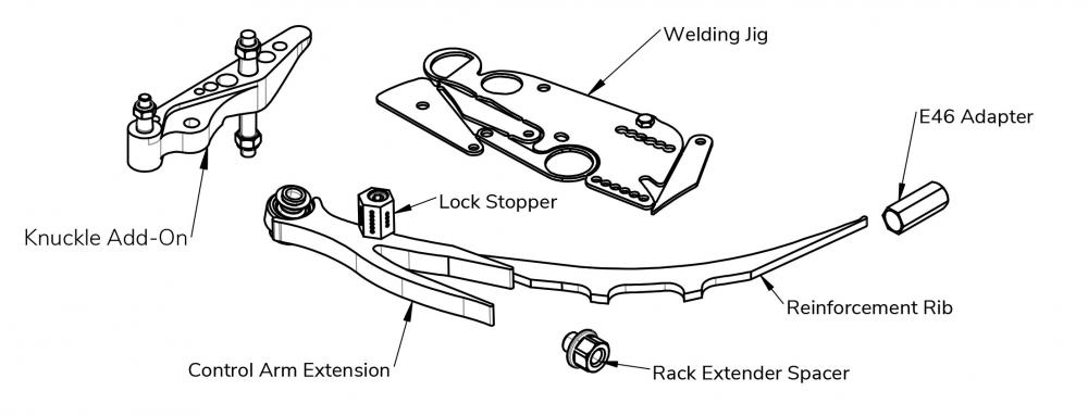
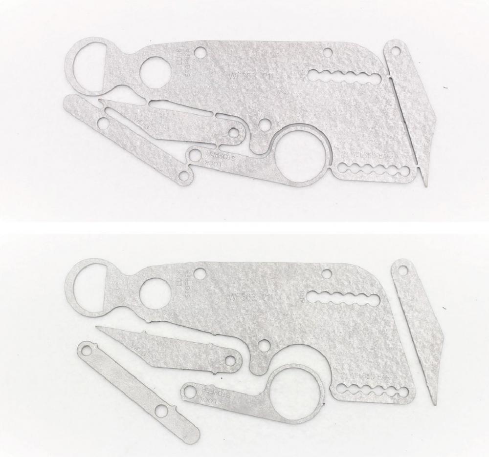
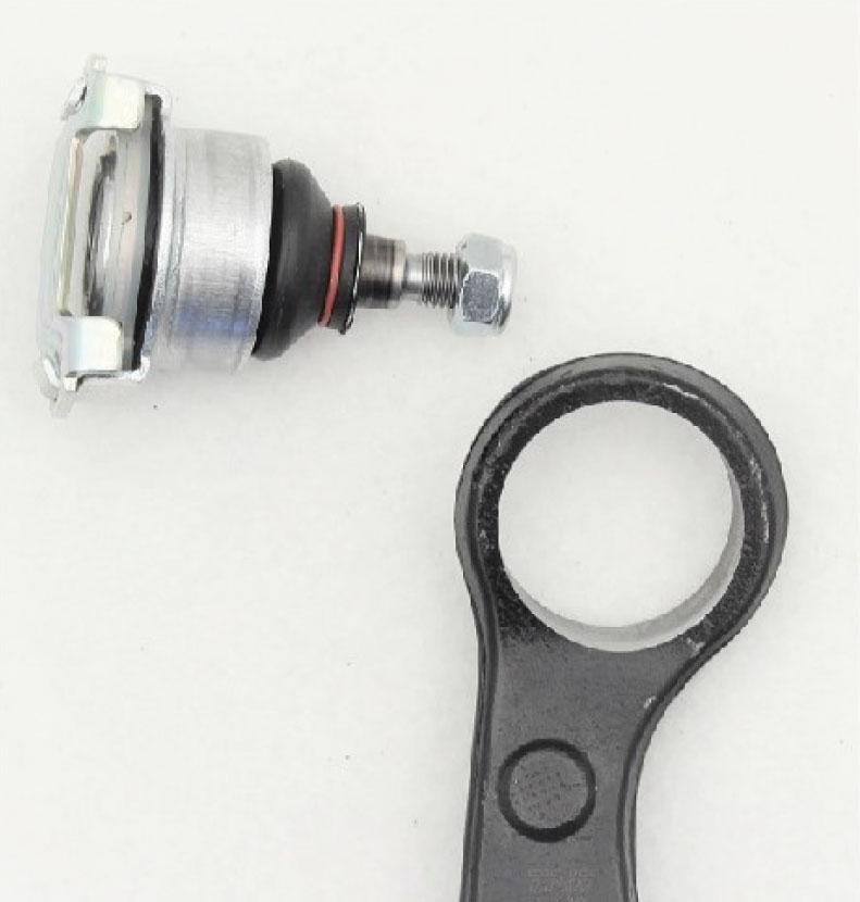
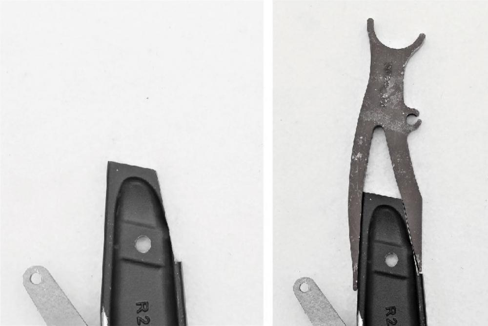
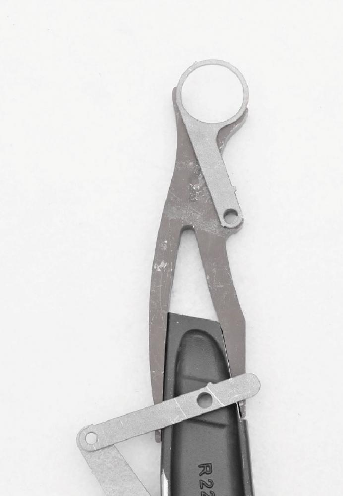
Cut apart the welding jig. Press out the outer ball joint.
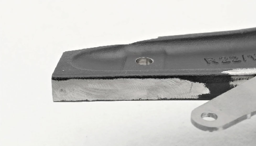
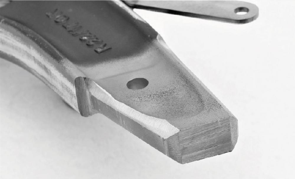
Grind away paint/rust from the highlighted area.

Installing the welding jig

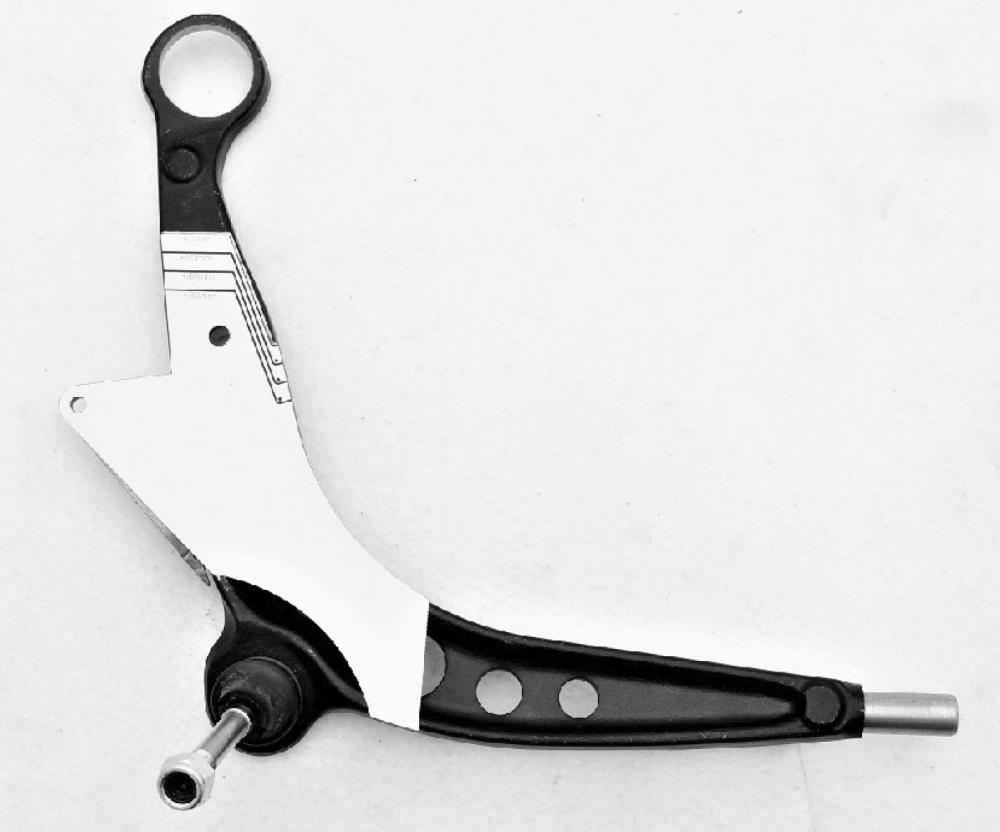
Install welding jig as shown on the picture. If there are higher casting marks on the control arm, grind them flat until the jig sits flat on the control arm. Make sure the jig is firmly situated in the ball joint bore. Push the jig in the direction of the arrow and attach it to the anti-roll bar mounting hole. Use the M10x55 allen head Lock Stopper bolt. Do not overtighten the bolt or the jig will deform!

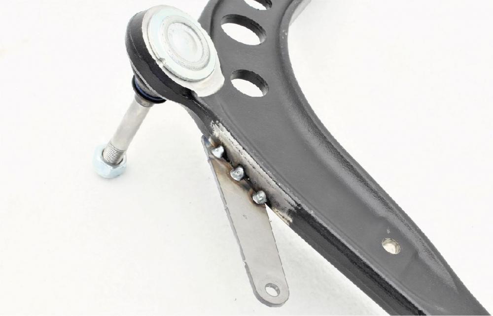
Attach one of the tabs to the jig as shown in the picture. Tack weld the tab from the underside and remove the jig.
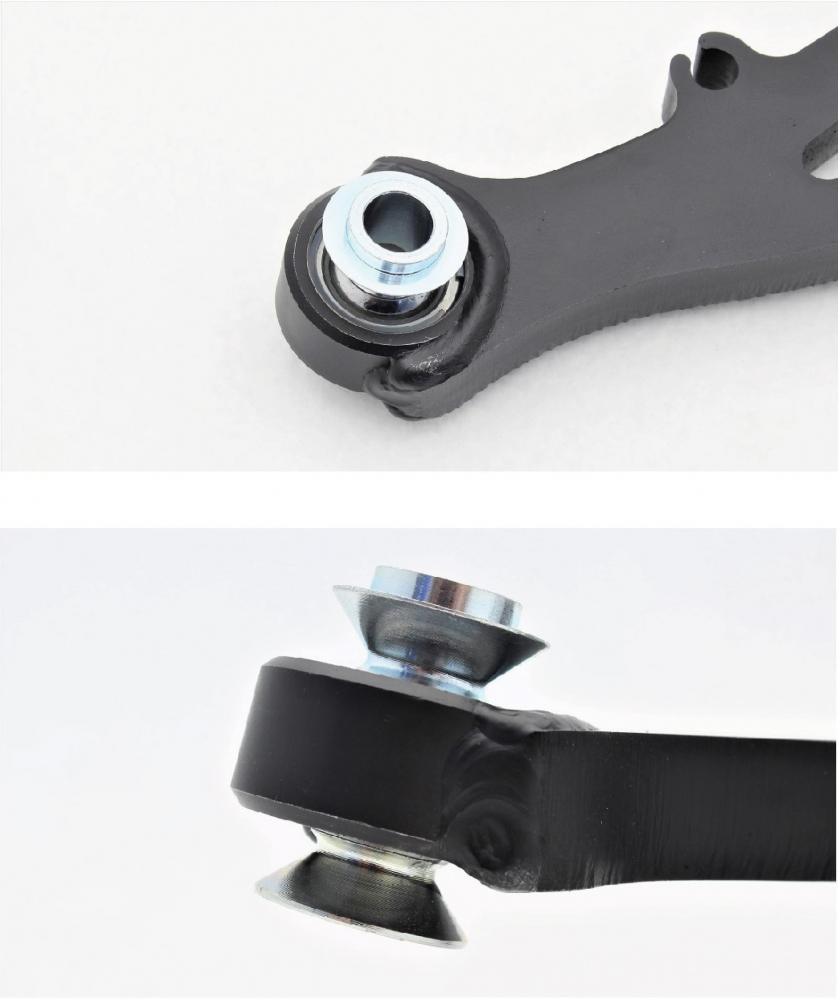
Installing the new outer joint housing.
Cut out the template at the desired control arm length and position it as shown in the picture. 60mm length shown in the picture.
Mark the cutting line and cut off the marked section.
Check fitment of the control arm extension. Use the welding jig to check fitment.
You may need to grind the outside of the control arm on some control arms.
Bevel the edges for welding.
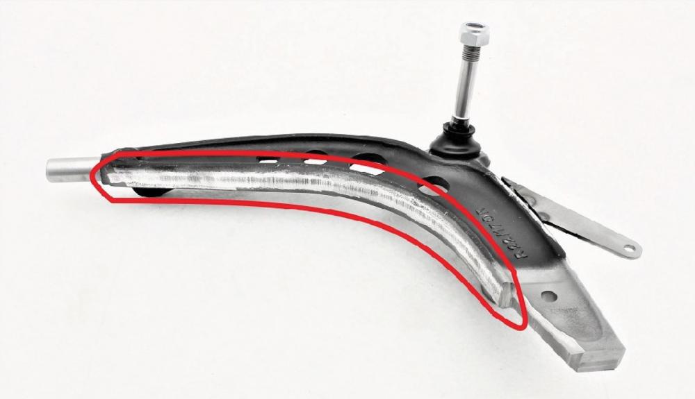
Clean the highlighted area from paint/rust.
Install spacers as shown in the picture.
Install the welding jig as shown in the picture. Use 2pcs M10x55 bolts and 1pc M8 bolt. Use the slot that corresponds to your chosen control arm length. 60mm length shown.
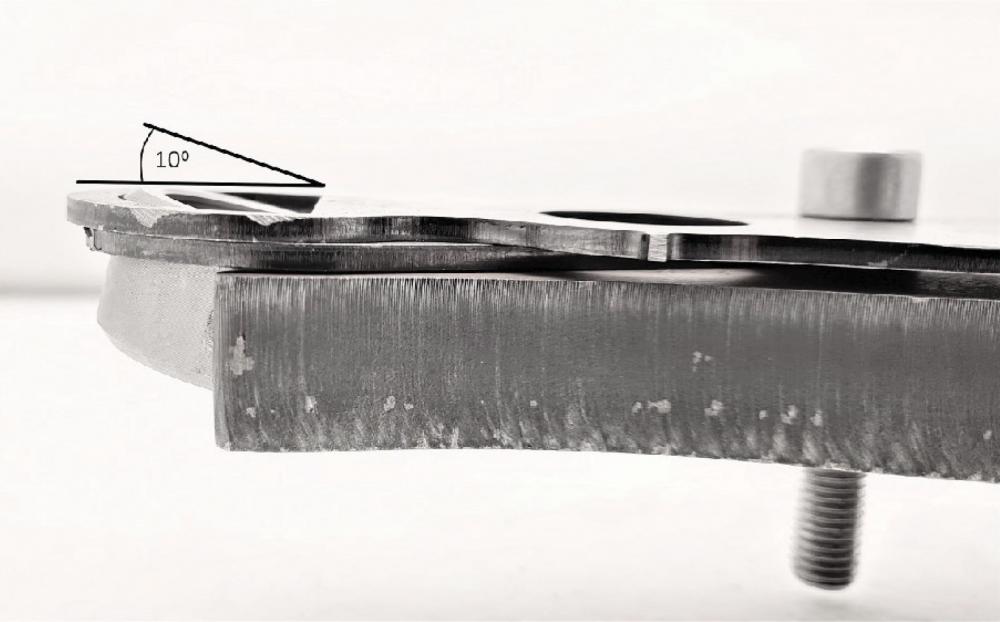
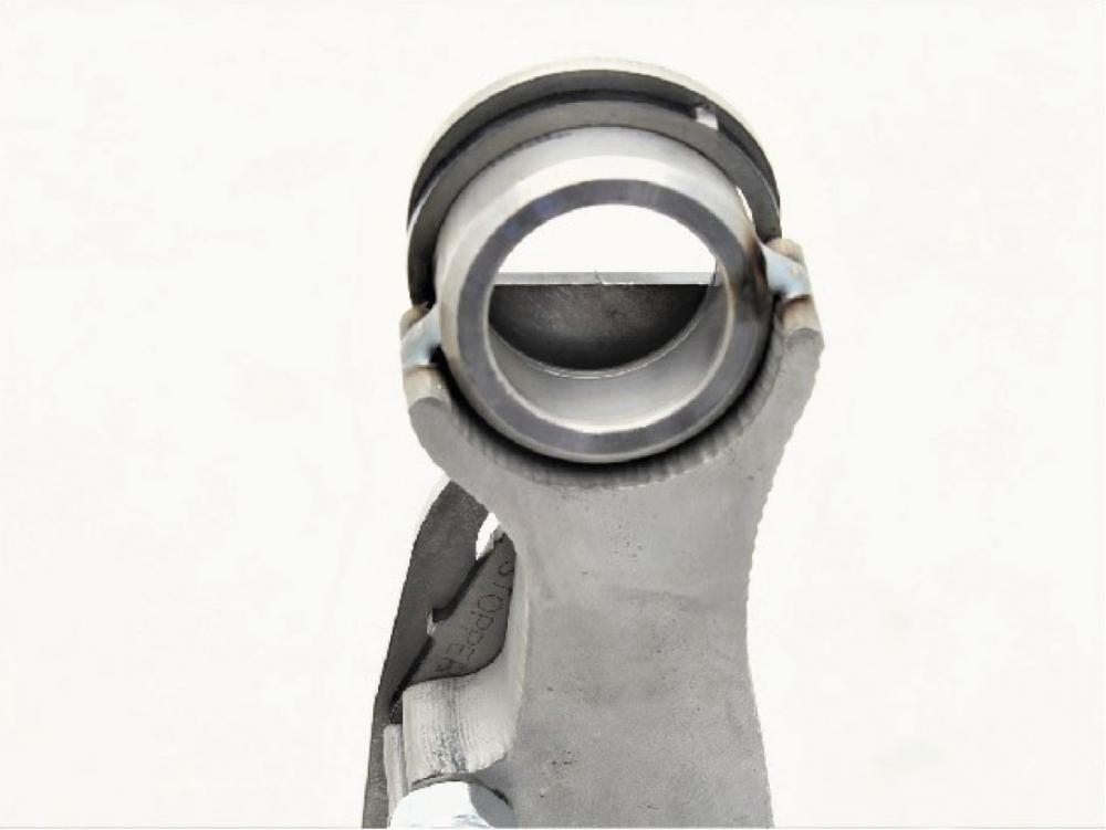
Tighten all bolts finger-tight and check fitment of the spherical housing. Fit the housing so that the circlip groove is at the top. Spherical housing should sit at a 10⁰ angle. 8 to 12 degrees is ok.
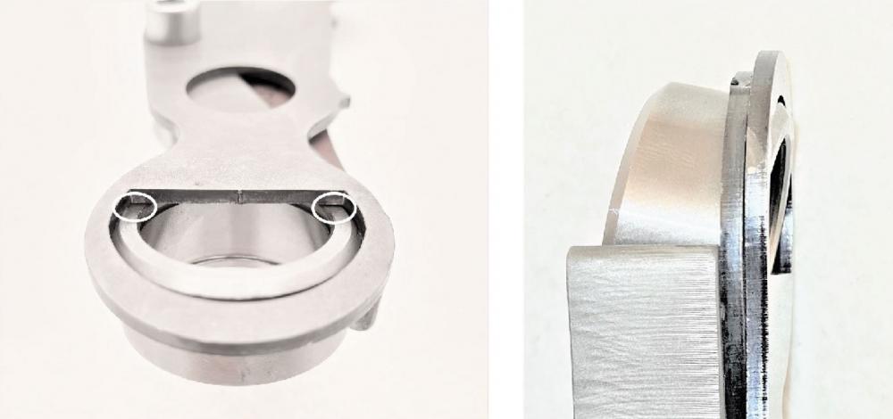
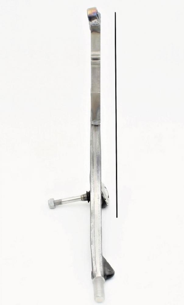
Make sure the extension is parallel to the control arm. Control arm shapes can be slightly different. Thus you may need to change the extension position accordingly.
Tack weld the extension to the control arm and spherical housing to the extension. Check the picture where you can find recommended points for tack welding.
Keep the jig in place and fully weld the control arm from one side. Do not overheat the control arm or the inner ball joint will become damaged. We recommend letting the control arm cool to room temperature before continuing. Remove the jig and the welded tab and fully weld the control arm.
Keep the jig in place and weld the control arm from one side. Do not overheat the control arm or the inner ball joint will become damaged. We recommend letting the control arm cool to room temperature before continuing.
Remove the jig and the welded tab and weld the control arm on the other side.
Installing the reinforcement rib
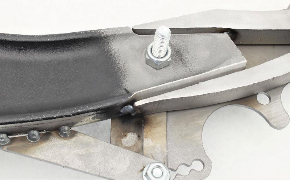
Check fitment of the reinforcement rib. If necessary, grind off the weld so that the rib sits as close to the control arm as possible.

If you are making control arms shorter than +60mm. Check the picture what type of modifications you need to make for the reinforcement ribs.

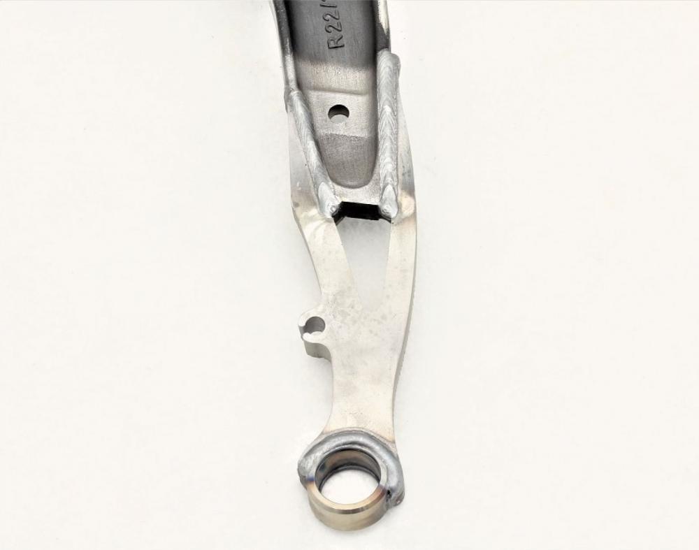
Make sure the rear end of the reinforcement rib sits flush with the control arm as shown in the picture. If not, grind some material off the rib.

Make sure the rib is center and parallel to the control arm. Tack weld the rib.

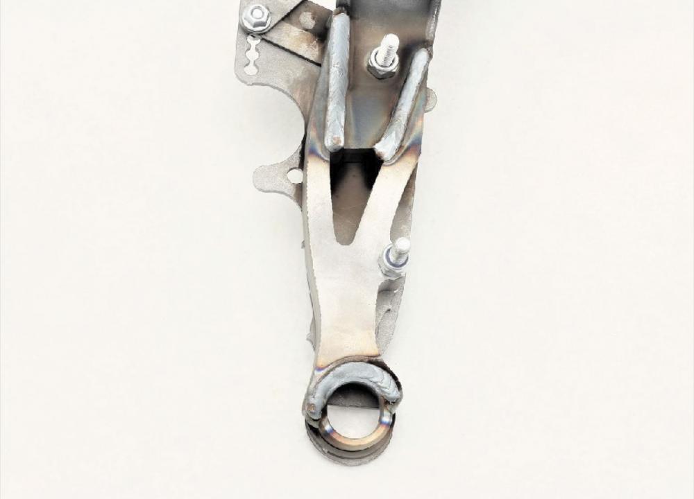
Fully weld the reinforcement rib. Do not overheat the control arm or the ball joint will become damaged.
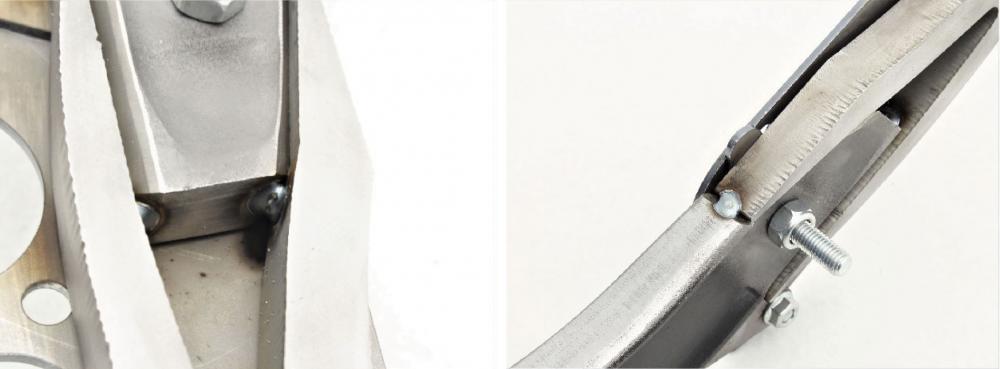
To install the control arm to E46, use the supplied hexagonal adapter. Fit the adapter so that one side of the adapter is parallel to the control arm/extension. Weld the adapter.

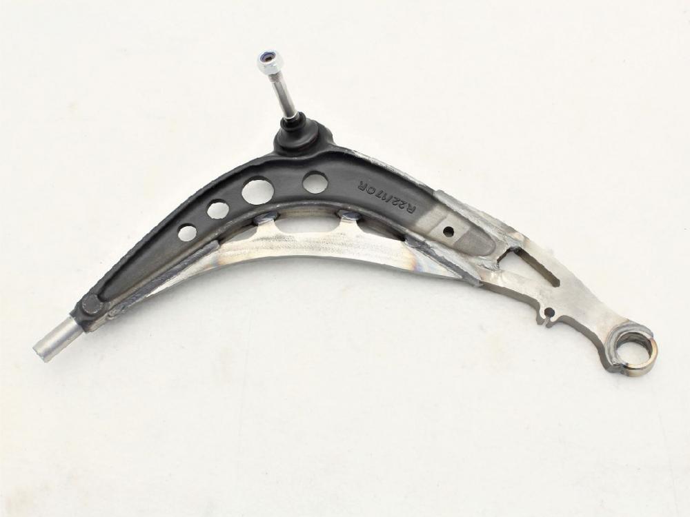
Paint the control arm to avoid corrosion.

Installing the hardware
Press in the spherical bearing. Press only from the outer race. You can use 22-24mm, 7/8" or 15/16" socket to press the bearing in. Fit the circlip. Press in the spacers so that the stepped spacer is on top. Install the lock stopper. Before installing the rack extender spacer, clean the threads inside the rack. After cleaning use thread lock on the spacer. Hold the rack shaft end firmly in place while torquing the spacer. For shorter than 50mm control arm length, the tie rod might need shortening. When assembling tie rods, make sure the inner tie rod has at least 13mm or 1/2 inch of thread engagement in the tie rod end.